

ESP32-P4 board
A dual-core RISC-V ESP32-P4 board, with selectable chip revision, mask ROM, PSRAM and flash
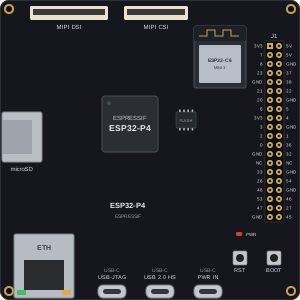
The ESP32-P4 board is a development board for Espressif’s ESP32-P4: two 32-bit RISC-V high-performance cores at 360 MHz (400 MHz on v3.x silicon) plus a low-power RISC-V core, with in-package PSRAM and external flash. The simulator runs the chip’s own mask ROM, so firmware boots through the same ROM → second-stage bootloader → application path as on the board.
It takes a merged flash image (.bin) written from offset 0, not an ELF — the same artifact esptool writes to a real board, containing the bootloader, partition table, and application.
The ESP32-P4 has no radio. The Wi-Fi companion chip many P4 boards carry (an ESP32-C6 over SDIO) is not simulated, so there is no Wi-Fi or Bluetooth on this board.
Datasheet
Section titled “Datasheet”The ESP32-P4 datasheet and technical reference manual cover the register map and peripherals. The board drawing’s 2 × 20 header follows the J1 header of Espressif’s ESP32-P4 Function EV Board.
Every pad on the chip is a pin, named by its GPIO number: GPIO0–GPIO54. That includes pads a real board routes to onboard parts rather than to its header. Power pins are 3V3, 5V and GND.
The J1 header (2 × 20) carries these:
| J1 pin | Signal | J1 pin | Signal |
|---|---|---|---|
| 1 | 3V3 | 2 | 5V |
| 3 | GPIO7 | 4 | 5V |
| 5 | GPIO8 | 6 | GND |
| 7 | GPIO23 | 8 | GPIO37 (U0TXD) |
| 9 | GND | 10 | GPIO38 (U0RXD) |
| 11 | GPIO21 | 12 | GPIO22 |
| 13 | GPIO20 | 14 | GND |
| 15 | GPIO6 | 16 | GPIO5 |
| 17 | 3V3 | 18 | GPIO4 |
| 19 | GPIO3 | 20 | GND |
| 21 | GPIO2 | 22 | GPIO1 |
| 23 | GPIO0 | 24 | GPIO36 |
| 25 | GND | 26 | GPIO32 |
| 27 | NC | 28 | NC |
| 29 | GPIO33 | 30 | GND |
| 31 | GPIO26 | 32 | GPIO54 |
| 33 | GPIO48 | 34 | GND |
| 35 | GPIO53 | 36 | GPIO46 |
| 37 | GPIO47 | 38 | GPIO27 |
| 39 | GND | 40 | GPIO45 |
Wire by the GPIO name, not the J1 position. Peripheral signals follow the firmware’s GPIO matrix and IO MUX setup, so a bus appears on whichever pads the firmware routes it to.
Configuration
Section titled “Configuration”| Key | Values | Default | Meaning |
|---|---|---|---|
revision | v0.0, v1.0, v1.3, v3.0, v3.1, v3.2 | v1.3 | Chip revision. v1.x cores run at 360 MHz, v3.x at 400 MHz |
rom | auto, rev0, v1, rev300 | auto | Mask ROM. auto uses the selected revision’s own ROM |
psram | none, 16MB, 32MB | 32MB | In-package PSRAM |
flashMB | 4, 8, 16, 32, 64 | 32 | External GigaDevice flash size in MB |
const p4 = graph.addComponent("ESP32P4FunctionEV", { id: "p4", config: { revision: "v3.1", psram: "32MB", flashMB: 16 },});await p4.setFlash("./build/merged-binary.bin");v1.x and v3.x images are not interchangeable, on silicon or here: pick the revision your image was built for.
Firmware
Section titled “Firmware”Build with ESP-IDF 5.4 or 5.5 and merge the image:
idf.py set-target esp32p4idf.py buildidf.py merge-bin # writes build/merged-binary.binesptool.py --chip esp32p4 merge_bin -o merged.bin @flash_args, run in the
build directory, produces the same image.
- v1.x revisions need
CONFIG_ESP32P4_SELECTS_REV_LESS_V3=y, the default in ESP-IDF 5.5. ESP-IDF 5.4 builds v1.x images only. - v3.x revisions need ESP-IDF 5.5.3 or later, built with
CONFIG_ESP32P4_SELECTS_REV_LESS_V3=n. - The ESP32-P4 bootloader sits at
0x2000, so a merged image starts with padding. Upload the whole merged image, notbootloader.binor the app.bin.
Peripherals
Section titled “Peripherals”These are simulated and have been checked with upstream ESP-IDF test apps and examples:
| Area | Peripherals |
|---|---|
| GPIO and timing | GPIO (including flex glitch filters and ETM), LEDC, PCNT, RMT, MCPWM, GPTimer, SYSTIMER / esp_timer, watchdogs |
| Serial buses | UART (including XON/XOFF flow control, autobaud, UHCI DMA), I2C master and slave, I3C, GP-SPI master and slave (including half-duplex quad), LP-SPI, TWAI/CAN ×3 |
| Audio | I2S (standard, PDM, TDM), LP I2S |
| DMA | AHB and AXI GDMA, DW-GDMA, 2D-DMA |
| Graphics and video | PPA, JPEG codec, H.264, MIPI-DSI display, MIPI-CSI camera and ISP, parallel LCD/camera (LCD_CAM), PARLIO |
| Storage | SDMMC (SD and eMMC), SD-SPI, flash (esp_flash, mmap, wear levelling, SPIFFS, NVS, OTA), PSRAM including execute-in-place from PSRAM |
| USB | USB OTG HS device (TinyUSB) and host, USB-Serial/JTAG including JTAG debugging with OpenOCD |
| Ethernet | EMAC with the IP101 PHY |
| Analog and sensing | ADC, temperature sensor, touch |
| Security | SHA, AES, RSA (MPI), ECC, HMAC, Digital Signature, ECDSA, flash encryption (XTS-AES), eFuse keys; Key Manager on v3.x |
| Power | LP core, light sleep, deep sleep and wake-up sources |
Debug output
Section titled “Debug output”| Channel | Description |
|---|---|
usbserial | USB-Serial/JTAG console — where ESP-IDF sends printf/ESP_LOG by default on this board |
uart0–uart4 | One channel per UART; uart0 is the console when firmware selects UART0 (GPIO37/GPIO38) |
Each channel streams to the terminal panel live and is readable afterwards with
run.logs({ from: "p4:usbserial" }).
Limitations
Section titled “Limitations”- No Wi-Fi or Bluetooth: the ESP32-P4 has no radio, and a board’s Wi-Fi companion chip (often an ESP32-C6) is not simulated
- Firmware has been tested with ESP-IDF; other frameworks have not